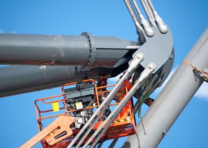
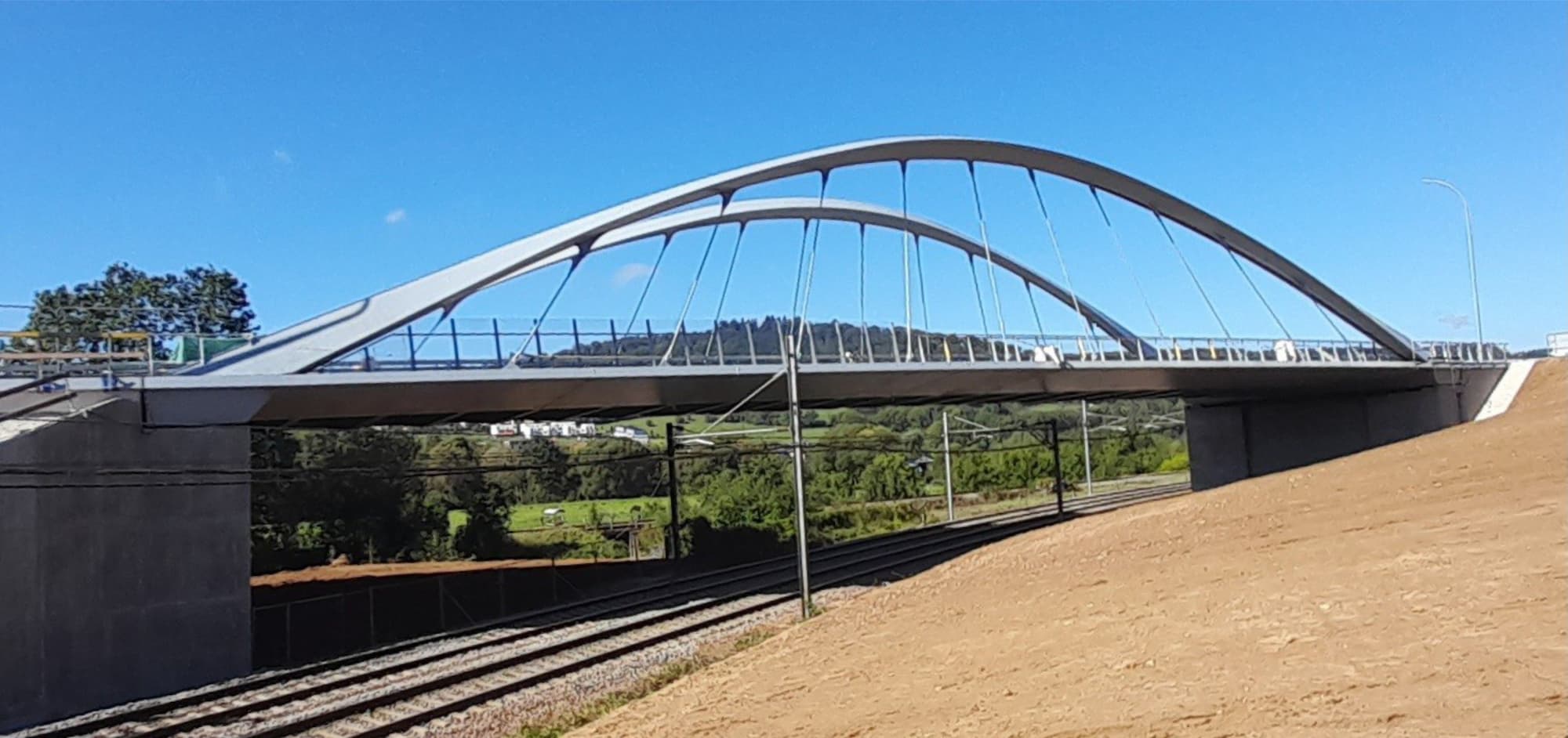
Meto Consult offers a range of structural tie-rod systems for all types of structures, whether stadiums, bridges, buildings, etc.
The tie bars range in diameter from M12 to M160 and can be supplied in carbon steel grades 355-S & 540-S and stainless steel grade E600-S.
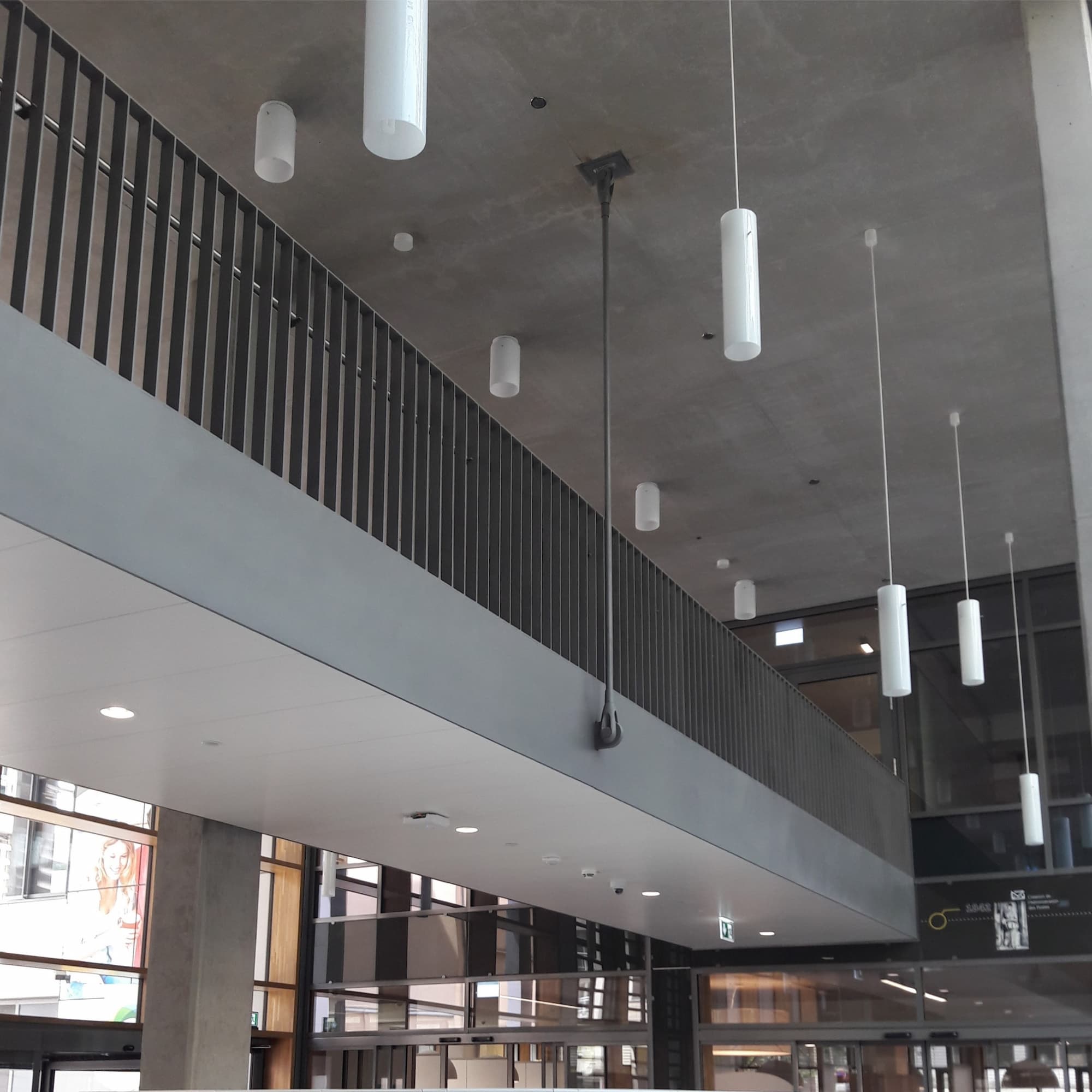
Discover other examples of architectural string
Tie bars can be supplied in two grades of steel:
Tie bars in carbon steel
Tie bars in stainless steel

All components are designed to exceed the capacity of the bar.
Discover the tables of admissible steel tendons
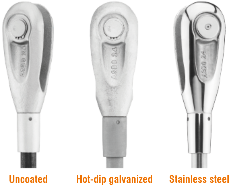
The systems can be supplied self colour or galvanised as standard.
Sizes up to M56 are supplied with forks, pins, turnbuckles, couplers and thread-cover sleeves hot dip galvanized as standard.
540-S bars M105-M160 are quench and tempered steel and therefore should not be galvanised.Bar threads can be formed after galvanising or are re-machined to size following galvanizing; repairs to the zinc coating are made in accordance with DIN EN ISO 1461. Spanner flats on the tie-rods are pressed following hot galvanizing to prevent brittle fracture.
Due to the nature of the galvanising process the visual finish of galvanised product is variable. If a high level of aesthetic finish is re-quired systems should be subsequently painted after a suitable primer has been applied. Tie bars cannot be supplied with "top-coat" finishes, this should be applied by the customer. Please advise us before placing an order if bars are intended to be painted.
Please contact us for more detail..
The components shown are generic and the design of pins, couplers and turnbuckles may change dependent on bar diameter.
Turnbuckles and couplers from M105 to M160 have a cross bore instead of spanner flat.
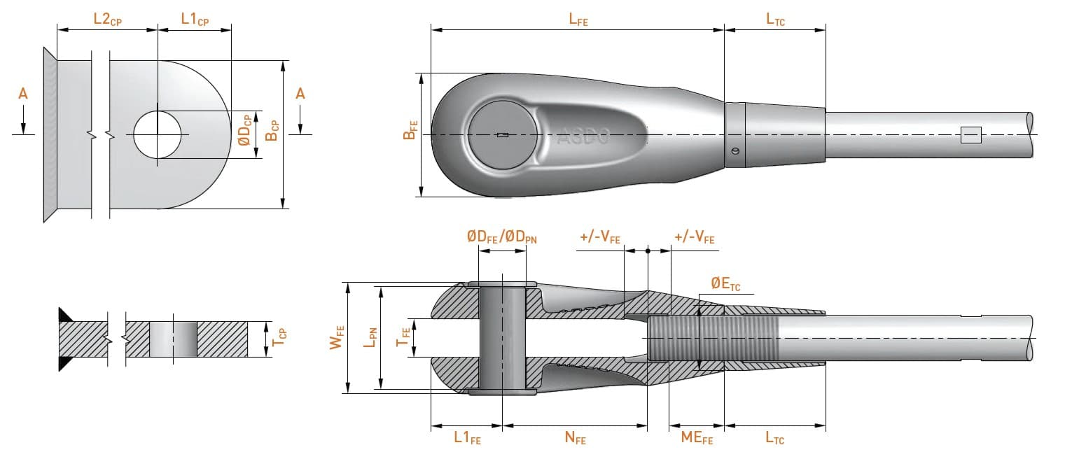
Discover the component dimension tables
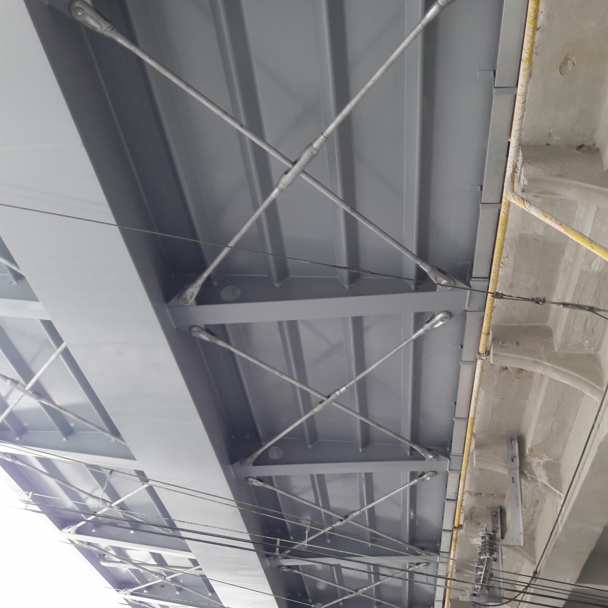
Tie bars bar can be used for cross bracing in a variety of ways but in all cases are easy to install and allow for In-Situ length adjustment to accommodate construction tolerances.
When selecting a bracing system the accessibility for installation and overall cost should be considered as well as the aesthetics.
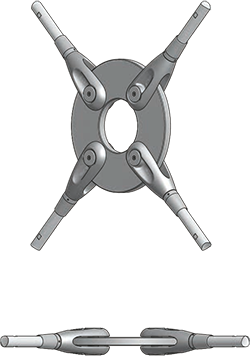
Bracing with centre disc
This is the most common system used as it offers the greatest flexibility and gives the best length adjustment ca-pabilities. It should be considered that double the number of clevises are re-quired compared to the other systems.
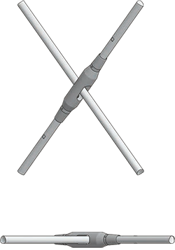
Bracing with cross turnbuckle
The cross turnbuckle can offer a more cost effective alternative to the centre disc, dependent on size, but gives limited in-situ adjustment. Further turnbuckles can be added for greater adjustment.
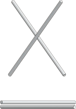
Bracing with crossed bars
If the tie rods can be offset from each other (ie are not in the same plane) then bars can be crossed as above. This is the most cost effective solution requiring the least components but has limited adjustment. Turnbuckles can be added to provide greater adjustment.
Discover the tables of the dimensions of the distribution discs and the turnbuckles with crossing hole.
The components are generic and the details of the pins, connection sleeves and turnbuckles may change depending on the bar diameter.
Turnbuckles and sleeves for M105 to M160 are designed with a side hole rather than a wrench flat.
See the technical instructions for compression struts

Consult the installation guide for the tendons systems.
The system can also be supplied with cold rolledthreads that gives bar threads a much greater resistance to fatigue than the standard cut thread.
Fatigue tests have been performed on full scale systems to over 2m cycles of loading without failing. We do not recommend hot dip galvanising rolled threads due to the increased risk of hydrogen embrittlement and much reduced fatigue resistance.
Please contact our technical department for further information regarding systems for use on structures subject to fatigue.
The system is manufactured under independently audited quality systems to ISO 9001 & EN1090 ensuring the require-ments of the ETA and CE marking are met.
The fork (or clevis) was developed using FEM techniques resulting in a very efficient load carrying design.
As most tension systems on the market fork connectors are made from cast steel. The ability of castings to transfer load from the structure to the bar is paramount and Anker Schroeder have a stringent quality control regime for the cast-ing process. All castings meet the requirements of EN10340.
Enhanced non-destructive testing can be offered by agreement. Please call our technical department for more detail.
To assist you in the design process we can supply component data in CAD and BIM format. For BIM this includes quality documents, installation manuals, brochures and design loads For CAD users we offer 2D and 3D files which contain most of the components. Individual components can be arranged into assemblies as required, only the individual tie rod length and restrictions to the angle of cross bracings need to be adapted to your project need.